
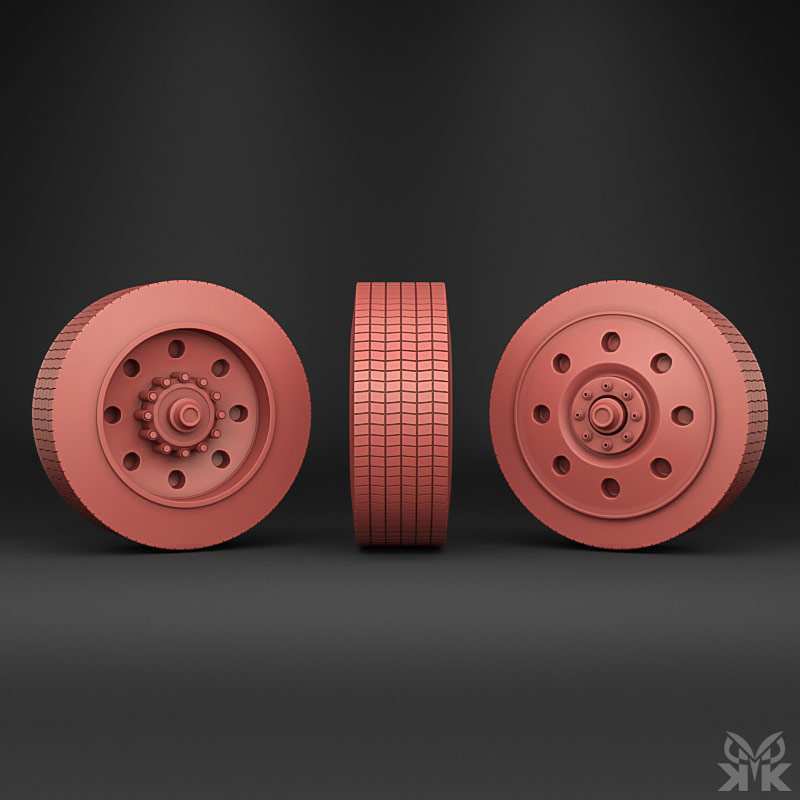
Simple Tire Modeling Technique of Peterbilt 389
Designed and Modeled in: Autodesk 3ds Max | Project Type: Tire Modeling Tutorial & Hard-Surface Vehicle Asset Development
Creating realistic tires is an essential skill for vehicle artists. While tire geometry may appear complex at first glance, most tread patterns are built from a small number of repeating elements. This tutorial demonstrates a straightforward workflow for modeling a Peterbilt 389 truck tire using Autodesk 3ds Max. By combining clean topology, modifier-based workflows, and careful planning, a detailed tire can be produced quickly while remaining easy to edit and optimize.
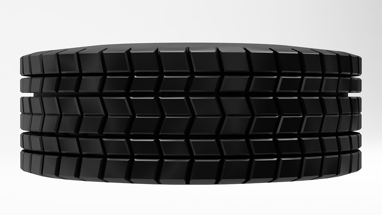
Every successful modeling project begins with reference analysis. Before creating any geometry, the tire’s proportions, tread arrangement, sidewall profile, and repeating pattern structure were studied. Understanding how the tread repeats around the circumference is critical, as it determines the entire construction process used later in the model.
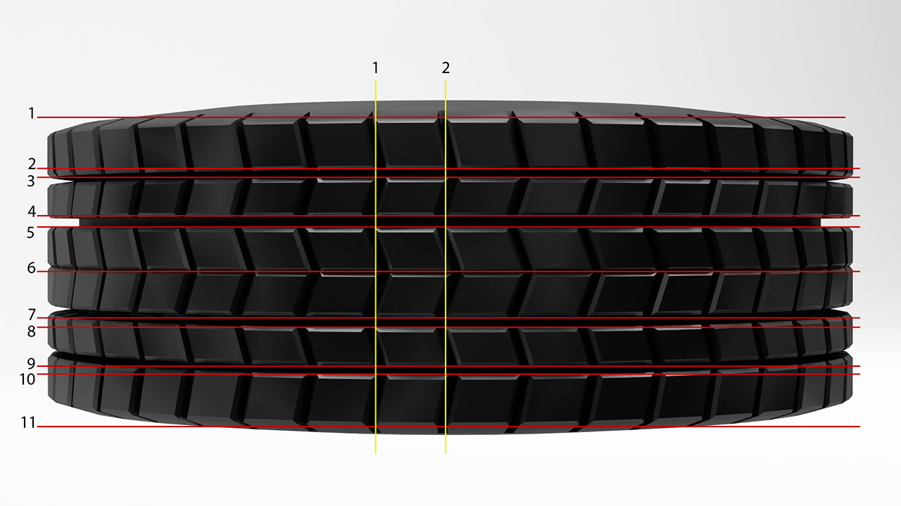
The tread was divided into repeating sections to identify the exact number of pattern repetitions required to complete a full tire circumference. Careful analysis at this stage prevents alignment issues later and ensures that the final tire can be bent into a seamless circular form without visible breaks in the tread design.
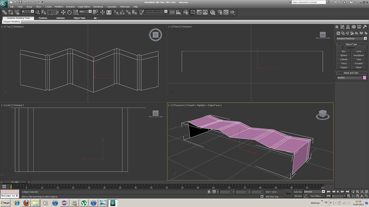
Modeling begins with a simple segmented plane that represents a single section of the tire tread. Working on a flat surface allows the tread pattern to be developed efficiently while maintaining clean topology and precise edge flow before any deformation is applied.
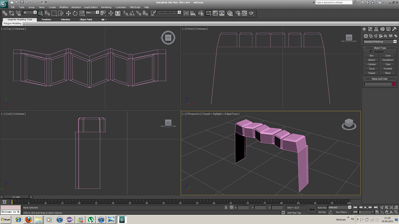
Once the basic pattern has been established, the tread blocks are extruded and refined using edge chamfers and supporting geometry. This process introduces depth, improves light interaction, and creates the sharp transitions necessary for a realistic truck tire appearance.
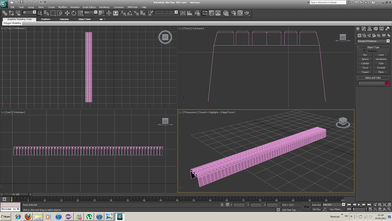
After a single tread section is completed, it is duplicated across the length of the strip to form the complete tread surface. Because every segment shares identical dimensions, the resulting pattern remains perfectly aligned and ready for transformation into its final circular shape.
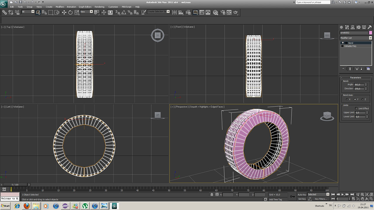
The completed tread strip is wrapped into a cylindrical form using the Bend modifier. This technique allows the tire to be constructed from a flat pattern while maintaining consistent spacing between all tread blocks. Small adjustments to the bend angle help eliminate visible gaps where the first and last segments meet.
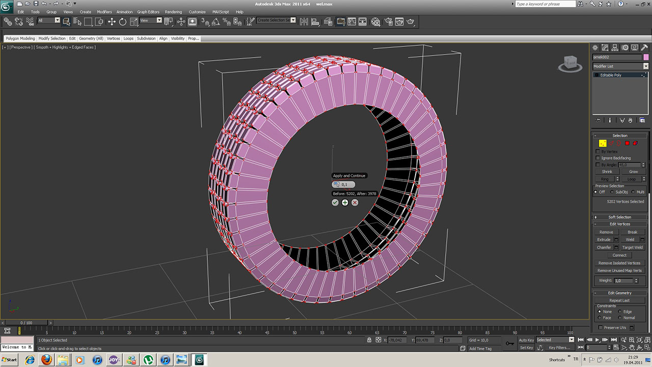
Following the bending operation, overlapping vertices are welded together to create a continuous mesh. Removing open edges and duplicate vertices ensures that the tire behaves as a single object and eliminates shading artifacts that might appear during rendering or subdivision.
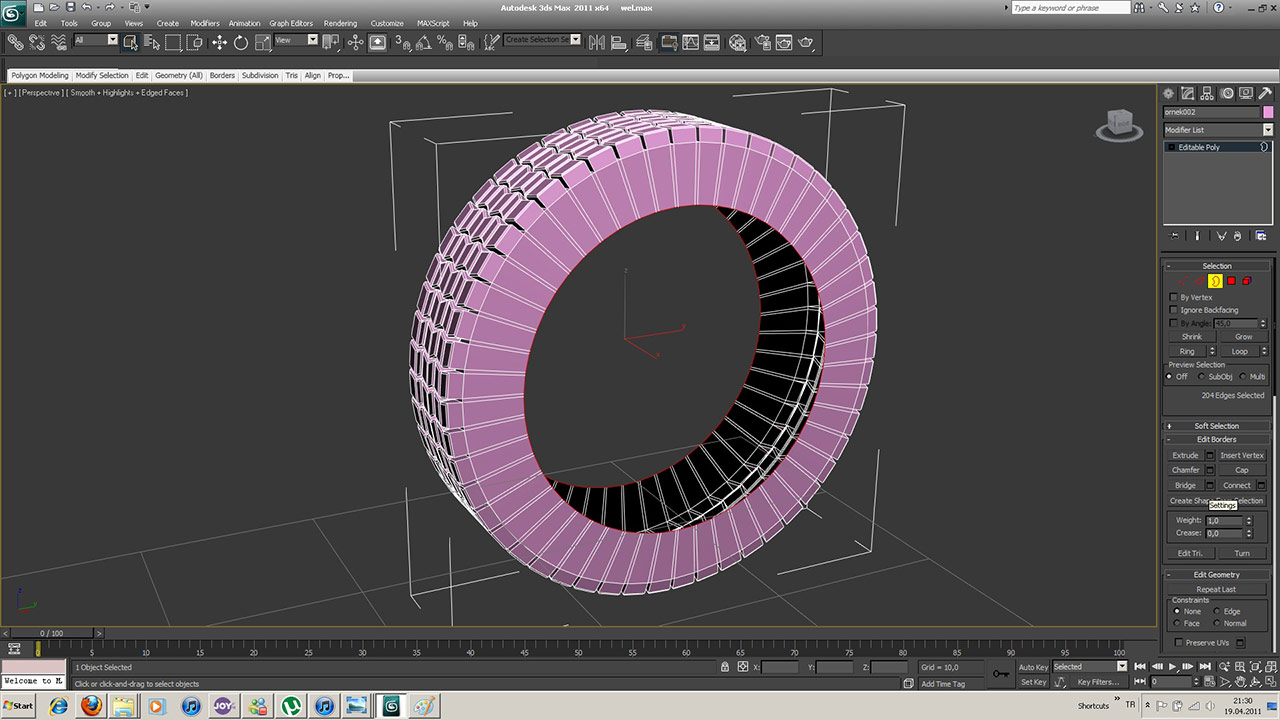
With the primary shape complete, thickness is added using the Shell modifier. This creates realistic sidewall depth and transforms the tread surface into a fully volumetric tire while preserving the efficiency of the original geometry.
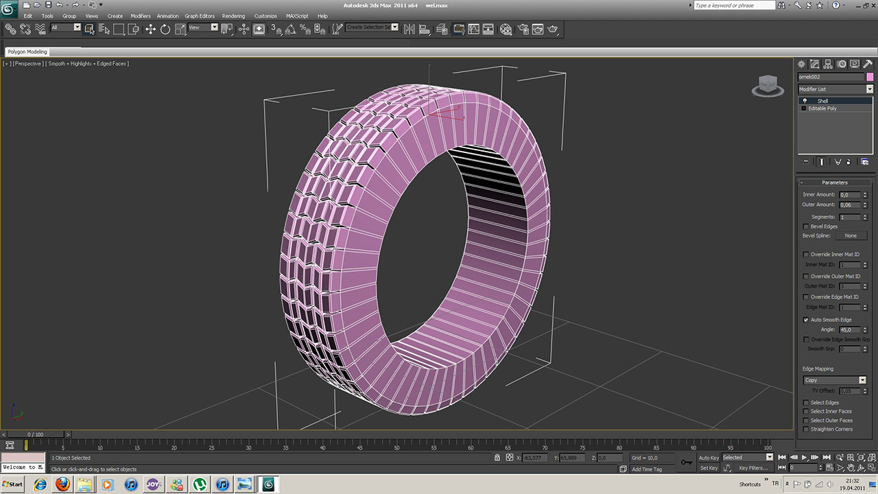
The finished tire demonstrates how a relatively simple repeating pattern can be transformed into a production-ready vehicle asset. The workflow remains fully editable throughout the process, making it easy to adjust dimensions, modify tread styles, or create variations for different vehicle types.
The Peterbilt 389 tire serves as an excellent example of efficient hard-surface modeling. Rather than building the tire directly as a complex circular object, the process focuses on constructing a clean linear tread pattern first and allowing modifiers to perform the heavy lifting. This approach produces accurate geometry, minimizes modeling time, and creates a flexible asset suitable for rendering, animation, visualization, or game development projects.
Related Keywords
Peterbilt 389, Tire Modeling, Truck Tire Design, Autodesk 3ds Max, Hard Surface Modeling, Vehicle Modeling, Tire Tutorial, Tread Pattern Modeling, 3D Truck Tire, Editable Poly, Bend Modifier, Shell Modifier, Automotive Visualization, Vehicle Asset Creation, Topology Optimization, 3D Modeling Tutorial, Truck Wheel Design, Digital Modeling Workflow, CG Modeling, 3D Visualization, Automotive Asset Development, Mechanical Modeling, Procedural Modeling, Rendering Workflow, Industrial Design
12 Comments