
Basic Modelling of Mecanum Wheel
Designed in: Autodesk Inventor | Unwrapped in: Autodesk 3ds Max | Project Type: Mechanical Product Design & Engineering Visualization Study
The Mecanum Wheel project was developed as a mechanical design study focused on recreating one of the most versatile wheel systems used in robotics and automated transport platforms. Unlike conventional wheels, a Mecanum wheel uses angled rollers to generate movement in multiple directions, allowing vehicles to move laterally, diagonally, and rotate without changing orientation. The objective of this project was to accurately reproduce the engineering principles behind the mechanism while creating a clean and presentation-ready digital model suitable for visualization, prototyping, and portfolio development.
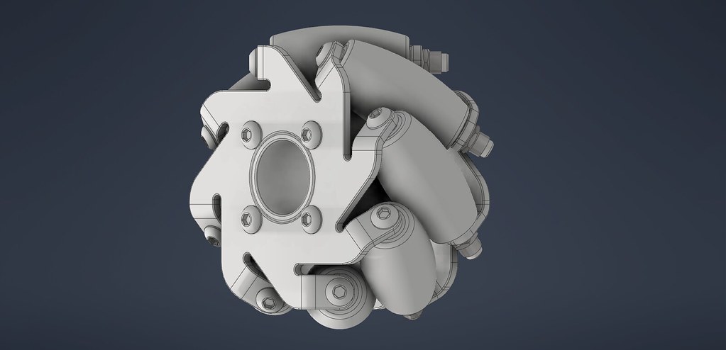
The completed wheel assembly demonstrates the relationship between the central hub, roller system, mounting structure, and fastening components. Every element was designed to function as part of a coherent mechanical system, ensuring that the wheel remains visually accurate while reflecting the engineering logic of a real-world Mecanum drive assembly.

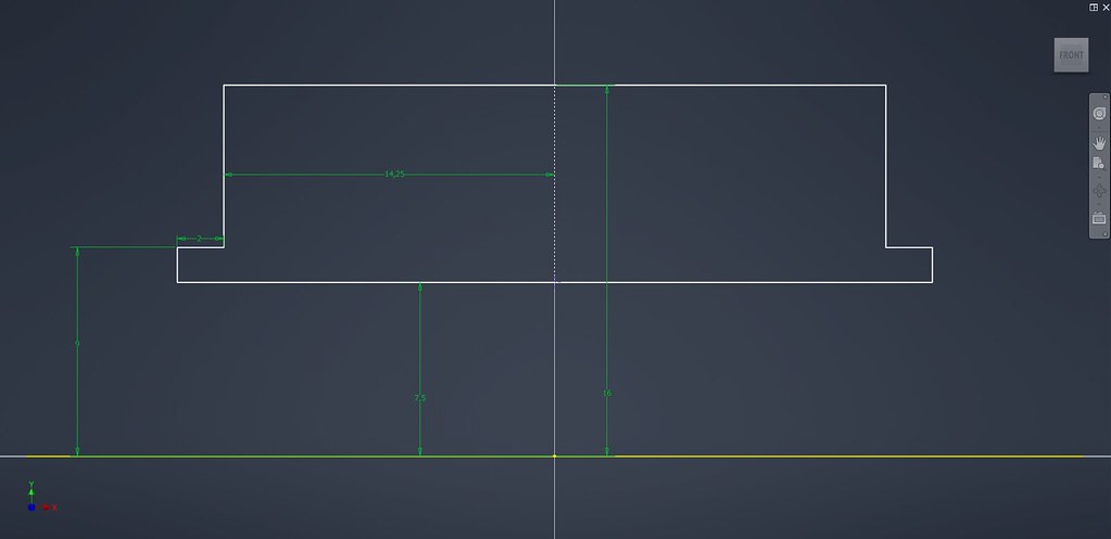
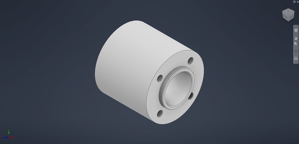
Development began with the creation of the primary mounting plate. This component establishes the foundation of the wheel and defines the location of every roller assembly. Careful dimensional planning at this stage ensured that the final wheel would maintain proper spacing, symmetry, and load distribution throughout the design.
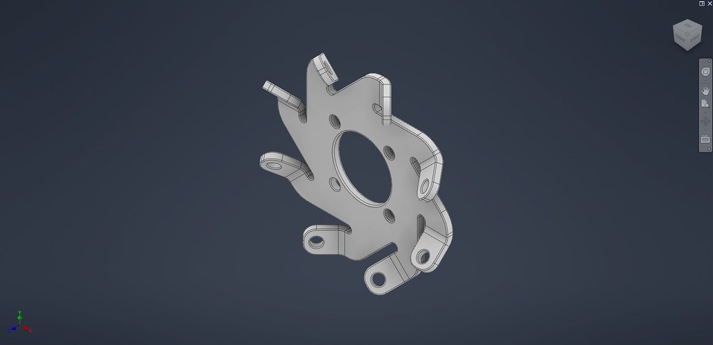
Once the core sketch was validated, it was transformed into a solid component through a series of parametric modeling operations. Establishing the base geometry early allowed the remaining assemblies to be developed around a stable structural framework while maintaining full control over future revisions.
The roller support system required its own dedicated design process. Each bracket was developed to provide accurate positioning, structural rigidity, and efficient load transfer between the rotating rollers and the central wheel assembly. Maintaining consistency across all brackets became essential because even small alignment errors would affect the overall behavior of the wheel.
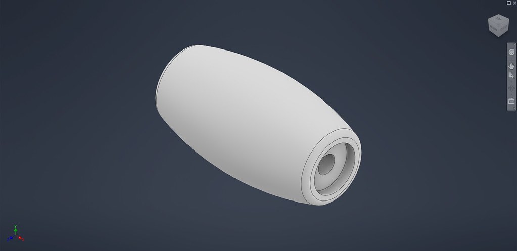
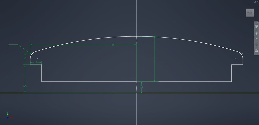
The rollers themselves were modeled as separate components to accurately represent their role within the mechanism. Their distinctive profile is responsible for the omnidirectional characteristics of the wheel, making their geometry one of the most critical aspects of the entire design.
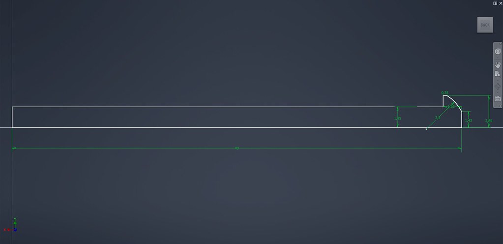
Supporting shafts were developed alongside the roller assemblies to ensure proper positioning and rotational freedom. Particular attention was given to dimensions, clearances, and assembly relationships so that the digital model would accurately reflect realistic engineering practices.
As individual components reached maturity, they were progressively assembled into functional subassemblies. This approach simplified validation and allowed each roller mechanism to be evaluated independently before being incorporated into the complete wheel structure.
Mechanical relationships between rollers, shafts, and support brackets were carefully reviewed throughout development. Verifying alignment, spacing, and rotational behavior helped ensure that the final assembly remained mechanically believable and structurally coherent.
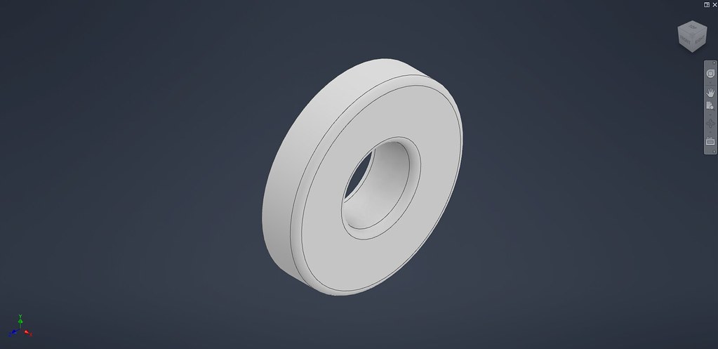
Additional supporting components were introduced to complete the wheel system and improve overall realism. Bearing surfaces, retaining features, and connection points contributed to the engineering fidelity of the model while enhancing its suitability for visualization and presentation.
The roller bracket evolved into one of the most important structural elements within the assembly. Beyond simply holding the roller in place, it acts as a critical interface between moving and stationary components, influencing both durability and overall wheel performance.
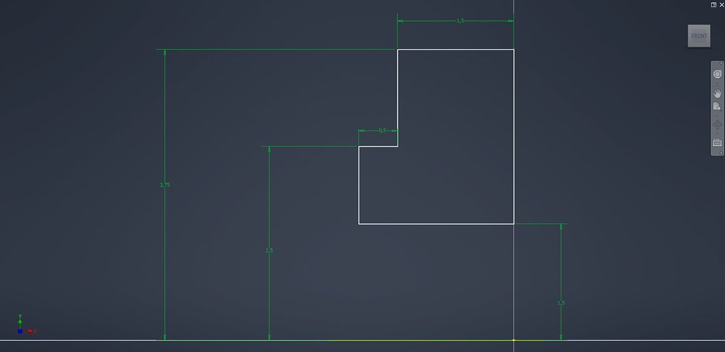
As the design matured, additional refinement focused on improving dimensional consistency and strengthening the relationships between neighboring components. Parametric modeling made it possible to adjust critical measurements while preserving the integrity of the entire assembly.
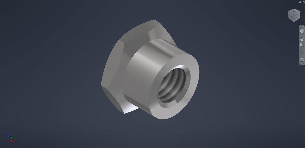
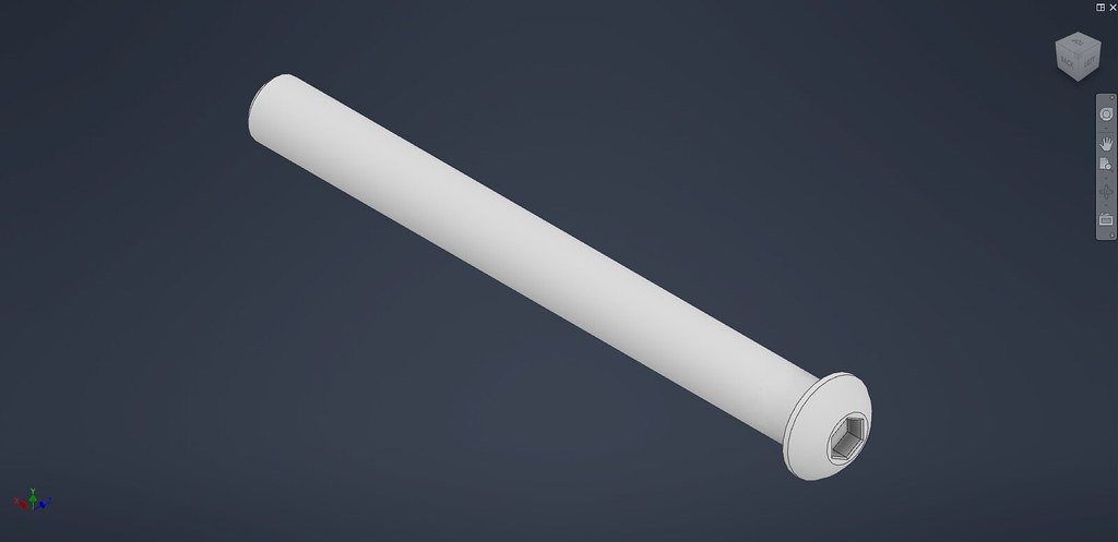
Fastener development formed an important part of the engineering workflow. Rather than using simplified placeholders, standardized mechanical hardware was incorporated throughout the model to reinforce realism and verify assembly feasibility. Including accurate fasteners also helped validate clearances, mounting positions, and manufacturing considerations.
The fully assembled wheel represents the culmination of the design process, bringing together every structural, mechanical, and fastening element into a complete engineering model. At this stage, the focus shifted from individual components to overall functionality, balance, and visual presentation.
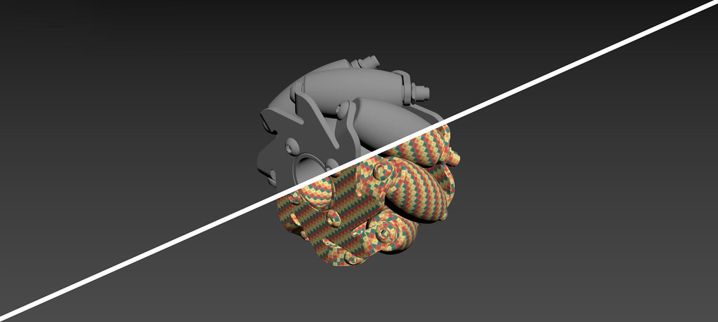
After the engineering phase was completed, the project moved into Autodesk 3ds Max for UV preparation and visualization. Clean UV layouts were created to support future material development and rendering, ensuring that the model could transition smoothly from engineering asset to presentation-quality visualization.
The completed Mecanum Wheel project demonstrates the value of combining mechanical engineering principles with digital visualization workflows. By developing each component individually and validating the assembly throughout the process, the project successfully captures both the technical complexity and practical functionality of one of the most innovative wheel systems used in modern robotics.
Related Keywords
Mecanum Wheel Design, Autodesk Inventor Modeling, Mechanical Product Design, Robotics Wheel System, Omnidirectional Wheel, Engineering Visualization, Mechanical Assembly Design, Parametric Modeling, Robotics Engineering, Wheel Assembly Development, Product Engineering, Mechanical CAD Design, Autodesk 3ds Max Visualization, Engineering Workflow, Industrial Design Project, Mechanical Modeling, Robotics Components, Engineering Asset Development, CAD Modeling, Mechanical Visualization, Product Development Process, Engineering Design Study, Robotics Mobility System, Digital Prototyping, Mechanical Product Visualization
No Comments