
Basic Modelling of Mecanum Wheel
The Mecanum wheel is one of the most unique and efficient wheel mechanisms ever designed for omnidirectional vehicles. Its angled rollers allow movement in any direction without changing the wheel’s orientation—making it ideal for robotics and industrial automation. In this project, I wanted to recreate a detailed 3D version of the Mecanum wheel using Autodesk Inventor for the mechanical modeling and Autodesk 3ds Max for visualization. The goal was to capture both the engineering accuracy and aesthetic precision of the real mechanism.

This image shows the final Mecanum wheel model in Autodesk Inventor. The wheel consists of a central hub, multiple angled rollers, and mounting plates. The design highlights how the angled rollers enable omnidirectional motion, allowing the wheel to perform complex movements such as sideways sliding and rotation.

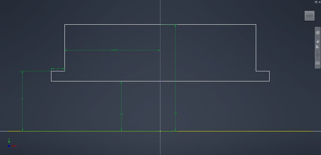
The modelling process begins with the creation of the base plate sketch. This foundational sketch defines the outer boundary and bolt holes for the mounting plate. Dimensions and constraints are applied to ensure geometric accuracy, forming the basis for the central hub where rollers and fasteners will attach.
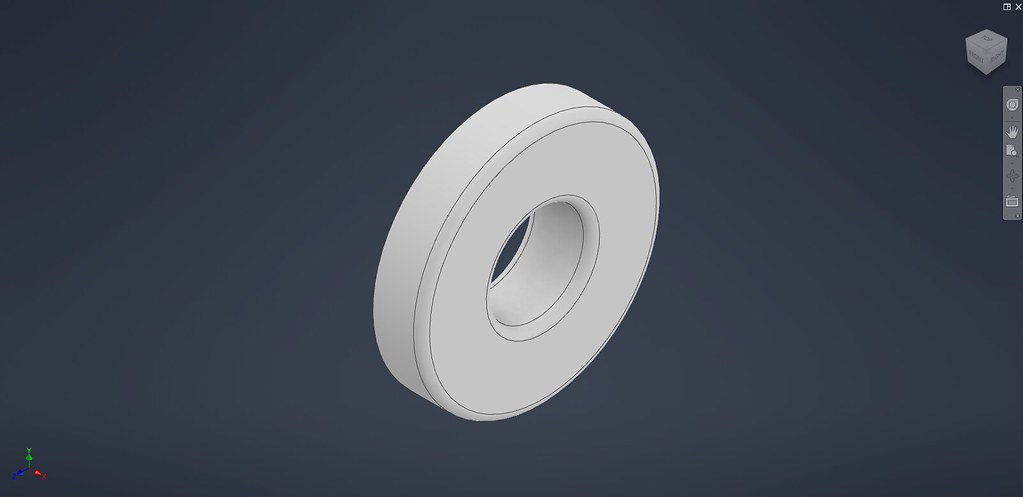
Once the sketch is finalized, it is extruded to create the physical body of the base plate. The extrusion thickness corresponds to the structural strength needed to support the wheel’s load. The resulting solid forms the central anchor for all subsequent components.

This sketch shows the outline of the roller bracket — the small support that captures the roller and transmits loads into the base plate. The sketch defines the bracket flange shape, the hole pattern for its fasteners, and the boss that centers the roller shaft. Dimensions are established so the bracket aligns exactly with the roller spacing and bolt pattern on the plate.

The roller body is generated by revolving the 2D profile sketch around its axis. This step transforms the flat outline into a three-dimensional component. The smooth curvature ensures efficient contact with the surface during operation.

A cylindrical shaft is modelled to hold each roller in place. This shaft passes through the roller’s inner hole and connects to the main hub. The dimensions are optimized to allow free rotation while maintaining structural stability during movement.

The roller and its shaft are assembled together. This stage involves aligning the roller’s axis with the mounting shaft and constraining their motion appropriately. This ensures that the roller can rotate freely during the wheel’s operation.
This view shows a roller, its bracket and the shaft assembled together. Concentric mates and clearance checks ensure the roller rotates freely and has the proper axial play. If bushings or bearings are used they are modelled here and positioned between roller bore and shaft to illustrate real-world behavior.

The shaft is modelled as a short precision pin with defined bearing surfaces, an optional shoulder to locate axial position, chamfers for easy insertion, and tolerances for free rotation. Where required, the shaft includes a clearance hole or pressed-fit section, and length is chosen to allow a nut or retaining clip to secure the assembly without impeding roller motion. Materials, diameter, and surface finish are selected to balance strength with low friction.
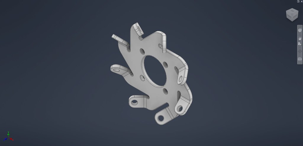
Here, the 3D model of the roller bracket is created by extruding the earlier sketch and adding necessary features such as fillets, chamfers, and bolt holes. The bracket’s function is to hold the roller’s shaft securely while transferring motion and load back to the wheel hub. Attention is given to wall thickness and reinforcement ribs to provide enough stiffness without adding unnecessary weight. This part is key for maintaining mechanical accuracy, as it defines the roller’s position, axis alignment, and load distribution across the wheel structure.
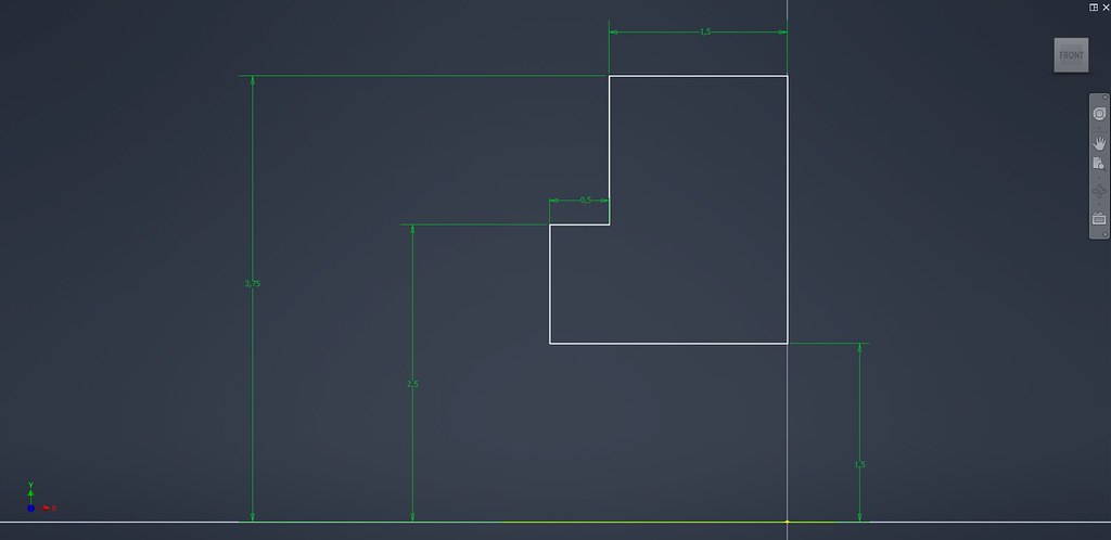
In this stage, the roller bracket’s base geometry is defined through a detailed 2D sketch. The sketch includes the bracket’s main profile, mounting holes, and the boss center point where the roller shaft will later attach. Dimensional constraints are carefully applied to maintain symmetry and alignment with the main plate. This sketch establishes the structural relationship between the bracket, the shaft, and the wheel hub — ensuring that each roller will be evenly spaced and properly angled when patterned around the assembly.

This image depicts the standard fastener used throughout the design: an ISO-compliant M3 bolt and mating nut (ISO 10511 specification). The bolt is modelled with the correct nominal thread length, head geometry, and shank clearance so that it seats properly in counterbores or threaded holes. Showing a standard part verifies that fastener lengths and countersink depths in the plate and bracket are correct and manufacturable.
The fully assembled Mecanum wheel is shown with all rollers, shafts, and bolts in place. The symmetry and mechanical alignment ensure balanced operation. The model accurately represents a real-world Mecanum wheel used in robotics and mobile platforms.

This last image belongs to the 3ds Max stage rather than Inventor: the model has been exported from Inventor, imported into 3ds Max, and the UVs have been unwrapped — the layout shows a clean, non-overlapping UV map ready for texturing (PBR or hand-painted). This indicates the model is prepared for material assignment, texture baking, and final rendering (lighting, displacement maps, and realistic materials) in the 3ds Max workflow.
The Mecanum wheel model shown here walks through the key mechanical design steps in Autodesk Inventor — precise sketched geometry, part modelling, bolt/fastener integration, shaft/bushing detail, and patterning to produce the functional wheel assembly — then transitions to 3ds Max for texturing and visualization. The approach balances engineering fidelity with presentation-quality visuals, making the model useful for both prototyping and portfolio work.
No Comments