

Chrysler K GF – Modelling Process in Inventor
Designed in: Autodesk Inventor | Modeled in: Autodesk Inventor | Visualization & UV Workflow: Autodesk 3ds Max | Project Type: Historical Tank Reconstruction & Hard-Surface Vehicle Design Study
The Chrysler K GF is one of the most unusual American tank concepts ever proposed. Developed in the mid-1940s, the vehicle featured a highly unconventional layout that placed major mechanical systems in positions rarely seen in traditional tank design. For this project, my goal was to reconstruct the vehicle as accurately as possible using available references, historical drawings, in-game assets, and technical interpretations. The entire model was created in Autodesk Inventor, allowing every component to be built with engineering precision before being prepared for visualization and rendering.
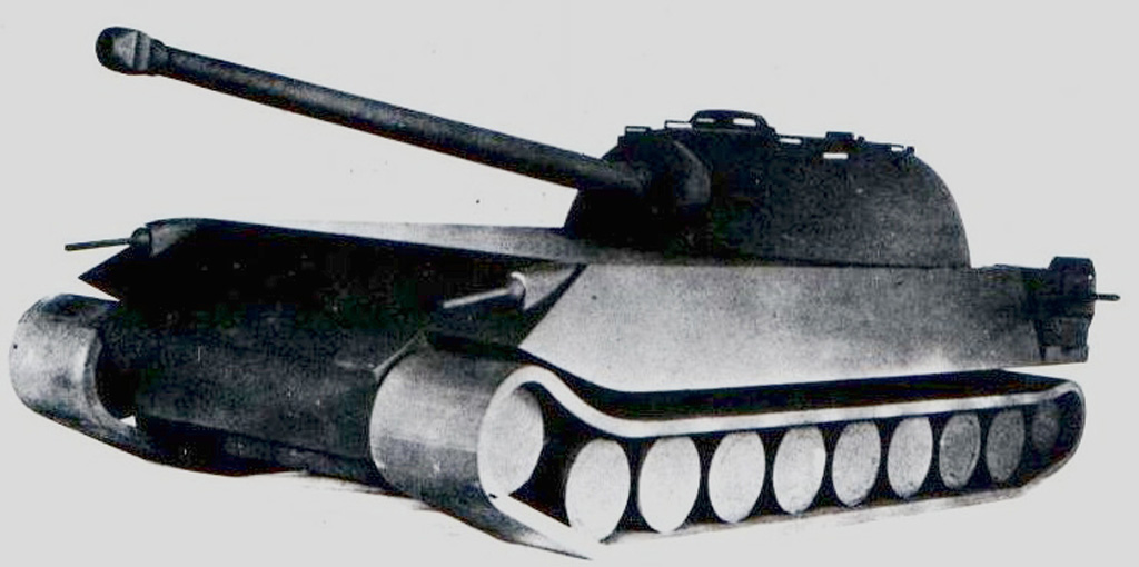
Every historical reconstruction begins with research. Because the Chrysler K never entered production, reliable references are extremely limited. Period photographs, technical illustrations, and community-generated reconstructions were collected and compared to establish the vehicle’s proportions, mechanical layout, and overall design language before modeling work began.
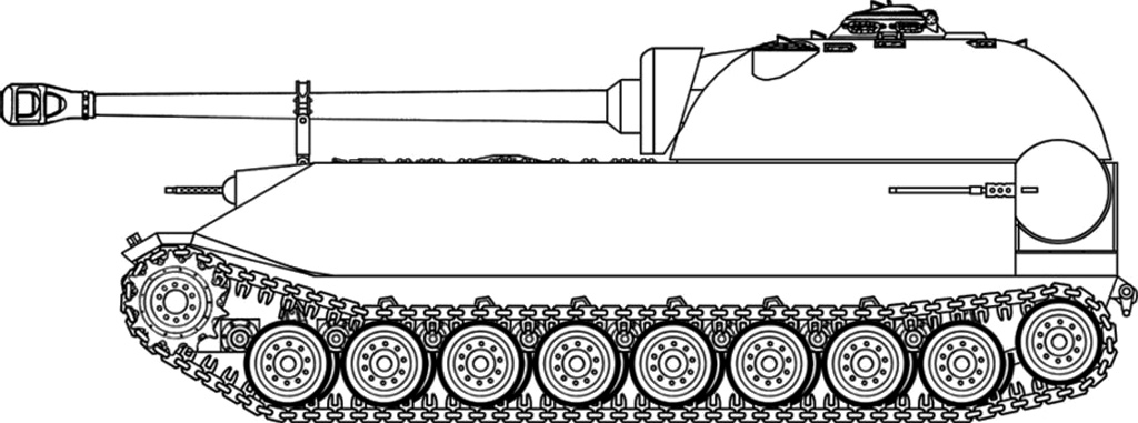
The side-view blueprint served as the primary foundation for the project. Major dimensions such as hull length, turret position, suspension spacing, and barrel placement were aligned to the reference drawing. Establishing these proportions early helps maintain consistency throughout the entire modeling process and minimizes scaling issues later in production.
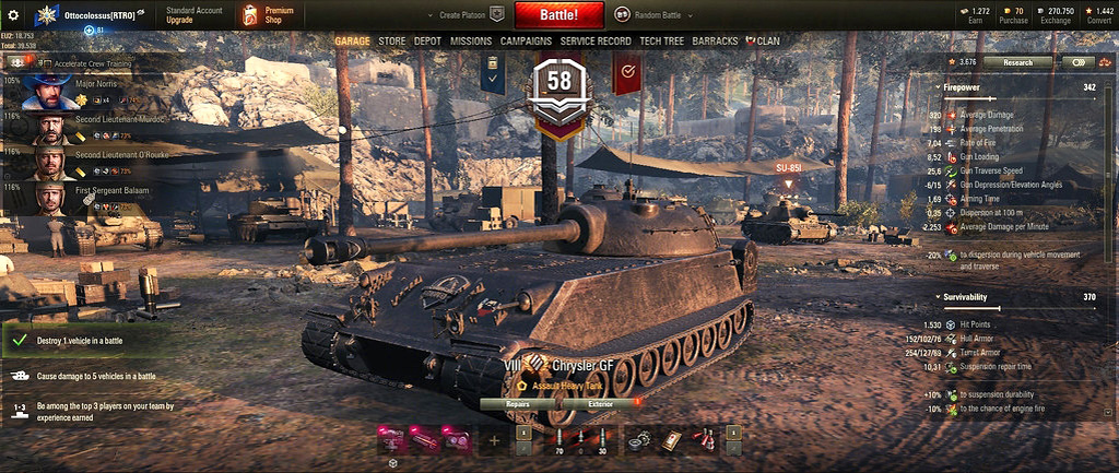
Additional references were gathered from World of Tanks, where the Chrysler K GF appears as a playable vehicle. These images provided valuable insight into details that were difficult to identify from historical photographs alone, including armor shaping, external equipment placement, and surface features visible from multiple angles.

Once the reference stage was complete, the primary vehicle forms were assembled. The hull, turret, suspension, barrel, and major structural components were positioned to establish the overall silhouette. This stage focuses on proportions and placement rather than fine detailing, creating a solid framework for later refinement.
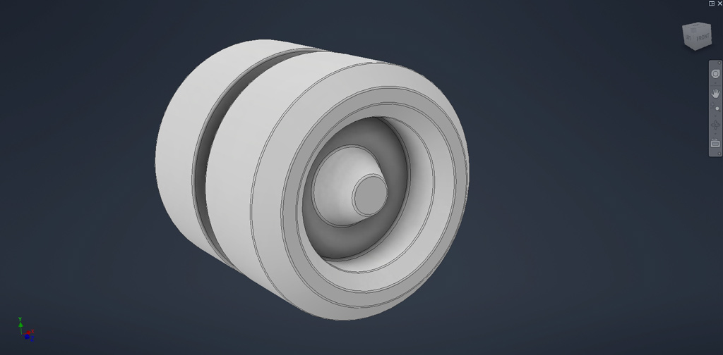
Road wheels were modeled as separate components to allow efficient reuse throughout the suspension system. Particular attention was given to profile accuracy, edge transitions, and dimensional consistency so that repeated instances would maintain a clean and realistic appearance across the entire vehicle.
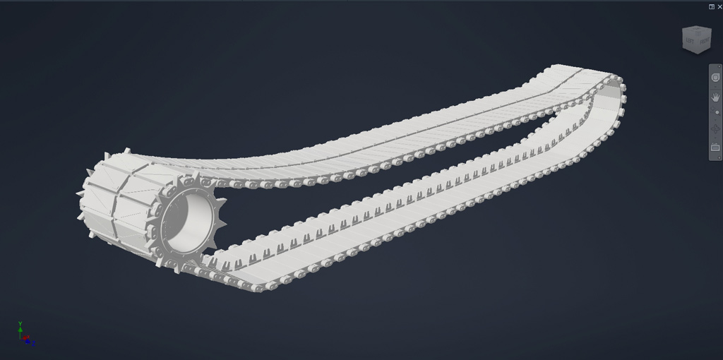
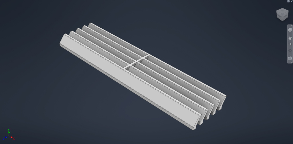
The track links were designed as modular elements that could be duplicated along the vehicle’s running gear. Building a single accurate track section first allows rapid assembly while ensuring that spacing, alignment, and mechanical relationships remain consistent throughout the suspension system.
This structural panel represents one of the many modular armor and support elements used throughout the tank. Creating individual components separately makes future modifications significantly easier and helps maintain a clean, organized assembly structure inside the Inventor project.
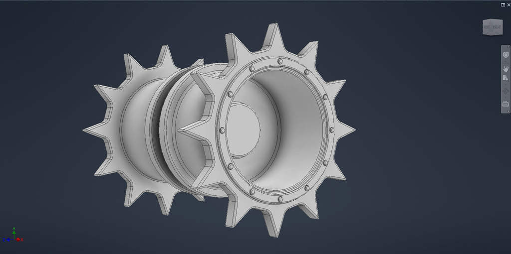
The drive sprocket was modeled to match the geometry required by the track system. Tooth spacing, hub proportions, and mounting details were carefully constructed to ensure proper interaction with the track links while preserving the distinctive mechanical appearance of the vehicle.
As the major mechanical components come together, the vehicle begins to transition from simple geometric forms into a recognizable tank. At this stage, constant reference checking becomes essential. Even complex shapes often originate from surprisingly simple forms, and careful observation helps reveal the underlying structure hidden beneath the vehicle’s exterior surfaces.
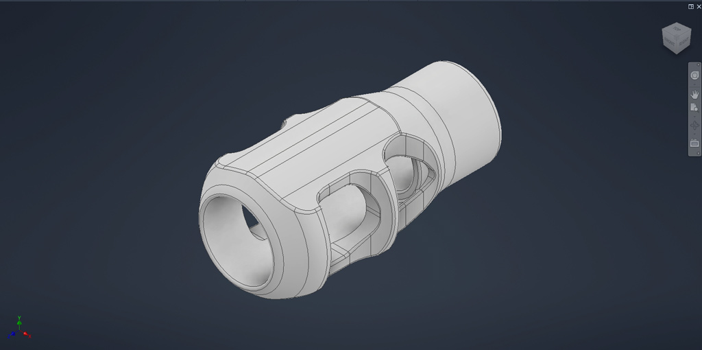
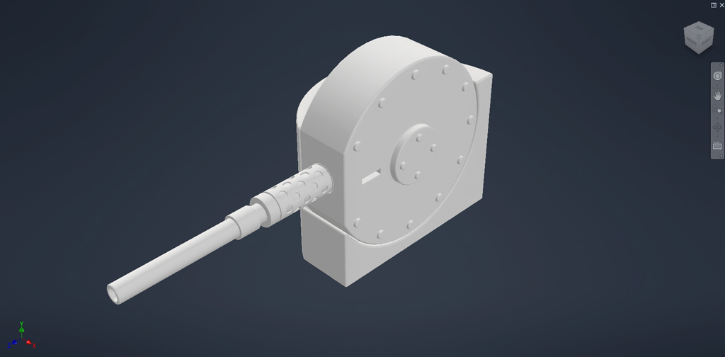
The muzzle brake was modeled as a standalone component to capture its unique geometry and internal openings. Features such as vent ports, edge bevels, and profile transitions were refined to ensure the part would hold up under close inspection while remaining faithful to the original design.
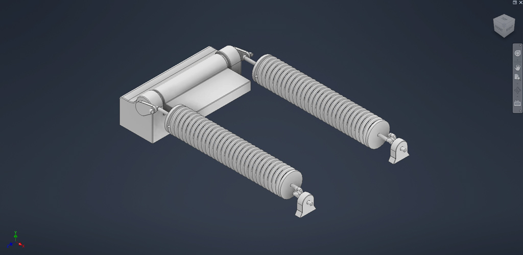
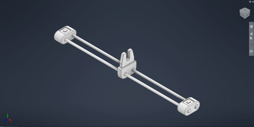
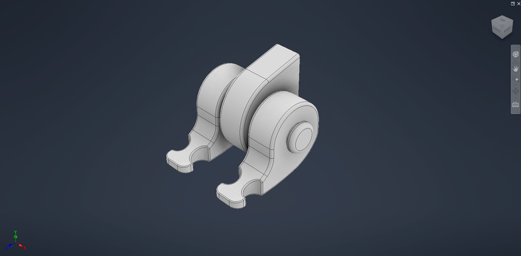
Mechanical support systems contribute significantly to realism. The commander hatch spring assembly was recreated to demonstrate how smaller functional components interact within the larger structure of the vehicle. These details add engineering credibility and help bring the model closer to a production-ready asset.
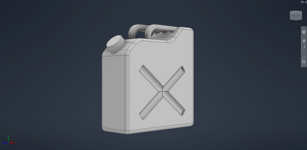
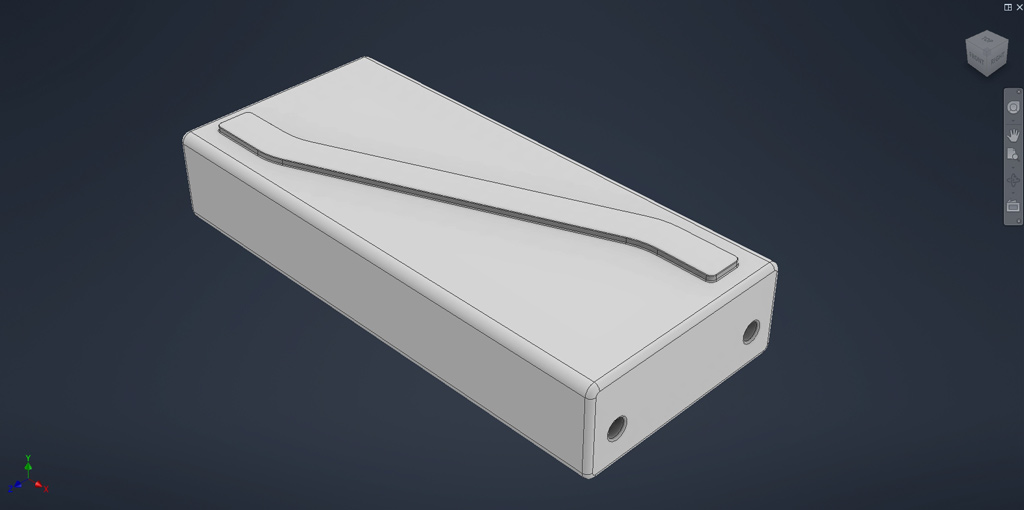
External equipment plays an important role in military vehicle design. The gasoline can was modeled as a separate reusable asset, allowing it to be positioned throughout the vehicle where additional storage or operational equipment would naturally be carried.
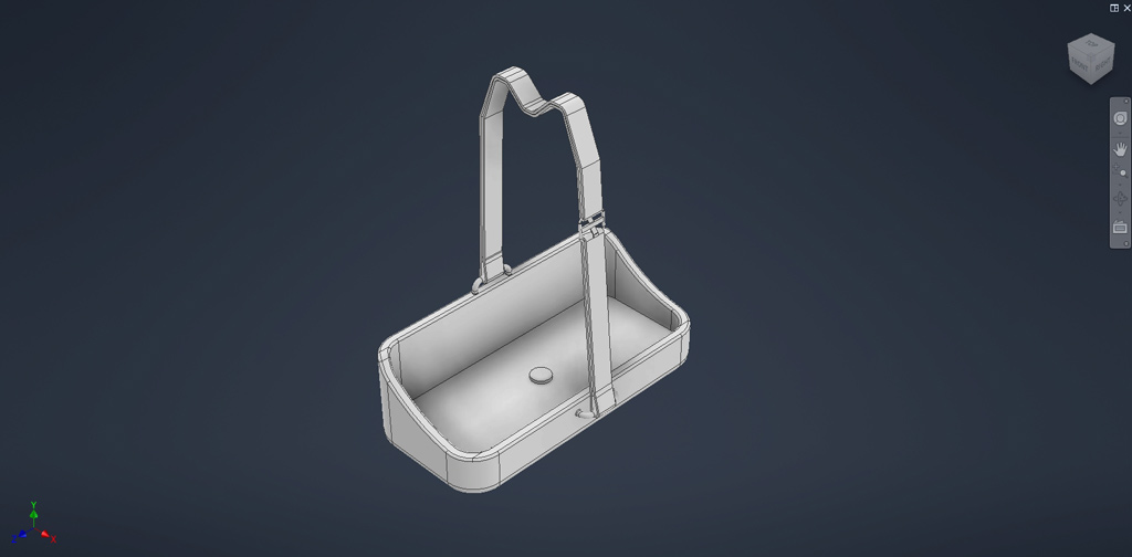
The holder was designed specifically around the dimensions of the fuel can to create a realistic mounting solution. Building accessories together with their supporting hardware helps ensure proper fitment and improves the overall authenticity of the final assembly.
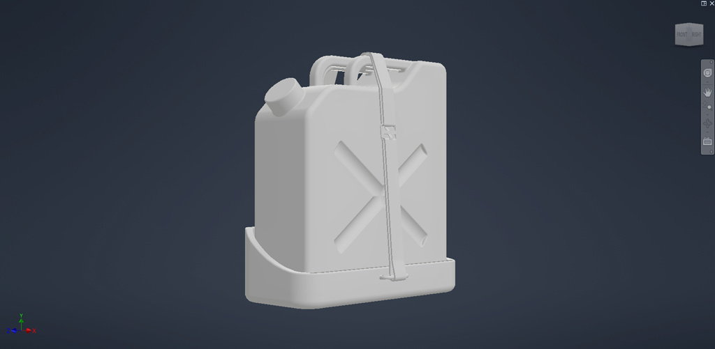
This assembled view demonstrates how multiple simple components combine to create a practical field-use storage system. Modeling these assemblies separately provides greater flexibility when arranging equipment and detailing the vehicle later in the project.
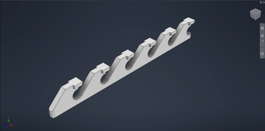
The engine deck grilles were developed as individual modules featuring repeated structural patterns. These components contribute visual complexity to the rear section of the vehicle while providing opportunities for detailed texturing, weathering, and material variation during rendering.
Lifting hooks are small but essential maintenance features found on armored vehicles. These parts were modeled as individual components and positioned according to reference material, helping reinforce the functional engineering aspects of the design.
Each track segment was built as a reusable modular component. This approach simplifies assembly, reduces modeling time, and allows the complete track system to be generated while maintaining accurate mechanical repetition across hundreds of individual links.
Secondary weapon systems were modeled separately before being integrated into the main assembly. Building reusable weapon components improves workflow efficiency while ensuring that smaller details maintain the same level of quality as the larger structural elements.
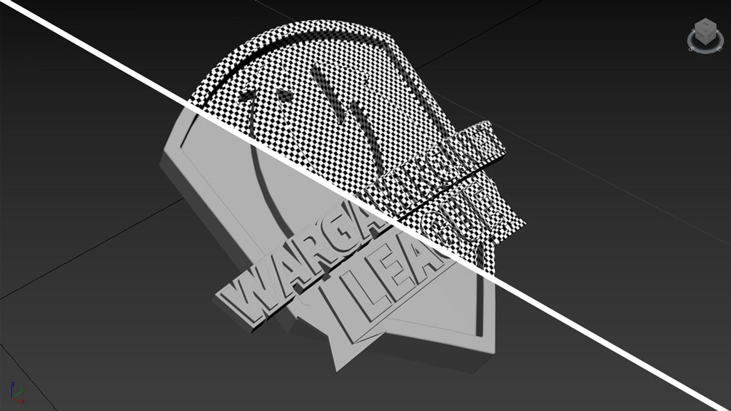
The Chrysler K GF variant features distinctive Grand Final branding created for Wargaming’s competitive event. After the modeling phase was completed, the logo was prepared separately for UV mapping and texturing, ensuring clean decal placement and accurate integration into the final vehicle presentation.
The completed assembly brings together every major subsystem, from the suspension and track system to the turret, armor plating, weapons, and external accessories. By combining engineering-based modeling with extensive reference analysis, the Chrysler K GF evolved from a collection of individual components into a cohesive and highly detailed digital reconstruction.
Related Keywords
Chrysler K GF, Chrysler K Tank, Cold War Tank, American Heavy Tank, Autodesk Inventor, 3ds Max, Hard Surface Modeling, Tank Modeling, Military Vehicle Design, Historical Vehicle Reconstruction, CAD Modeling, Mechanical Design, World of Tanks, Vehicle Visualization, Tank Blueprint Modeling, Digital Prototyping, Game Asset Development, Military Vehicle Visualization, Armored Vehicle Design, Engineering Workflow, Product Visualization, 3D Vehicle Modeling, Tank Asset Creation, Industrial Design, Automotive Visualization
No Comments